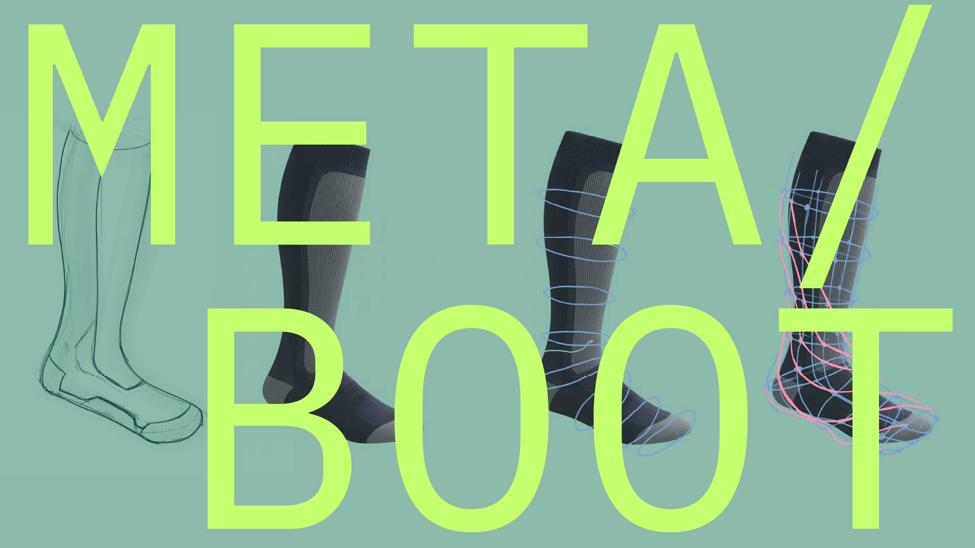
DRAWING A SKI BOOT
TL;DR
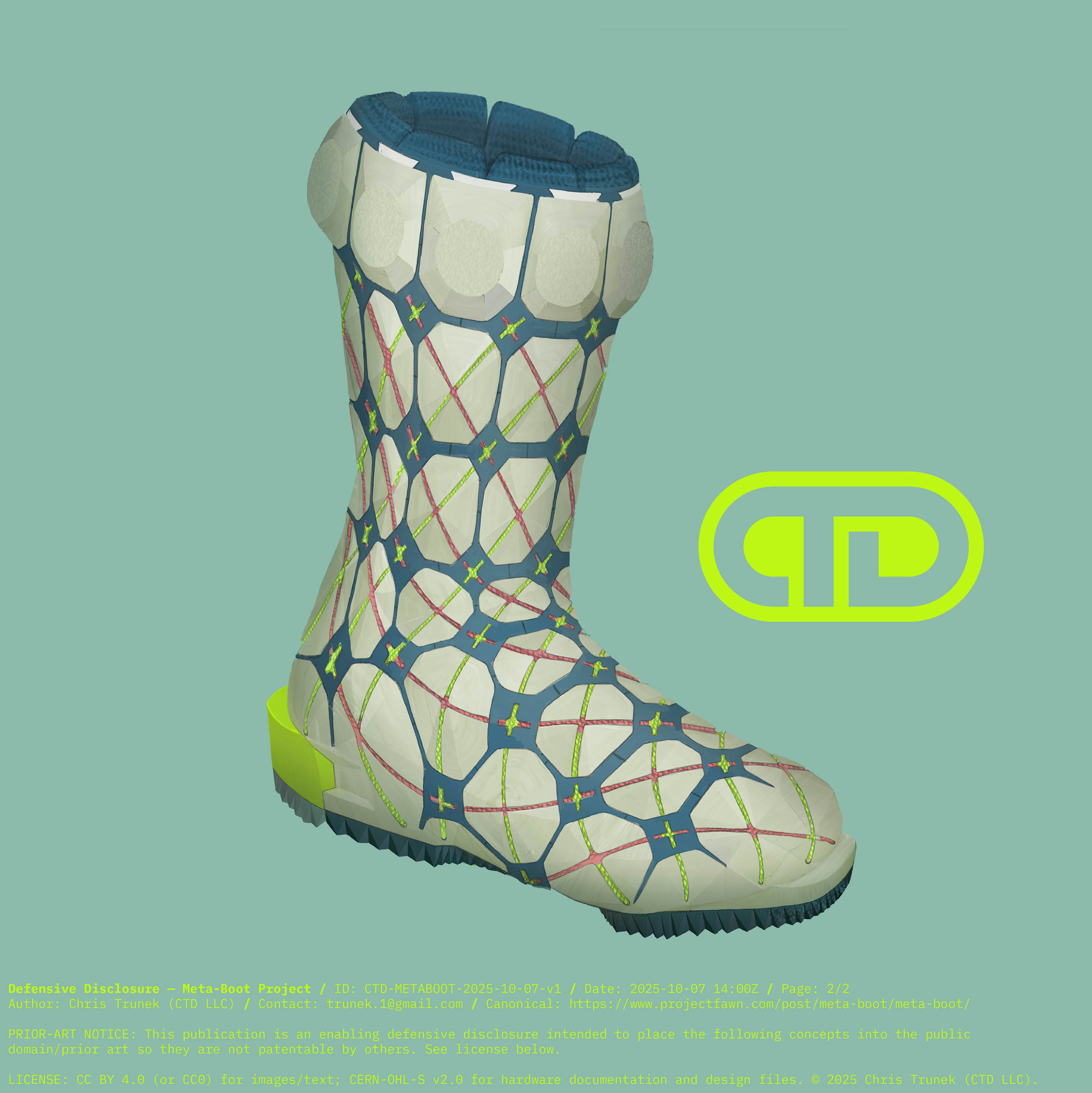
Defensive disclosure post: Concept art for tunable stiffness meta-tile based custom 3D printed ski boots with phantom-foot sensing, knee protecting releasable heel lugs
My previous explorations at drawing 3D printed concept boots always left me wondering, what was the closure system to tighten these things up and get them on and off? Without this critical detail, they could really only exist as vague ideas, not solidified visions. I explored all sorts of surrounding solutions, and just kept not seeing what was needed to close this loop.
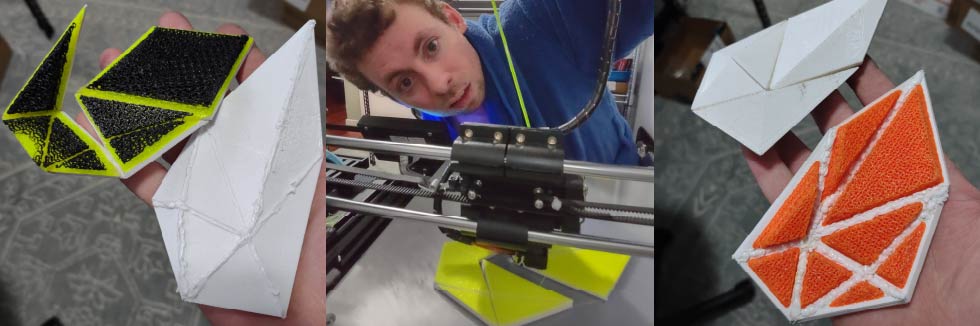
I had the thought of the paneled construction and figured I could test that idea further. I created a sample geometry of 8 triangular polygons to manually test modeling them. The process worked and it was straightforward but tedious to intersect and define all the mated edges. I 3D printed two sample tiles sets, both with the flexible TPU layers printed directly over top of the hard PETG tiles. With the green and black padded ones (dual densities) I tried folding thin connecting edges and bonding them with West Systems G-Flex epoxy. On the white and orange test, I used a 3d pen to weld the seams together. This was a better solution as it was more accommodating of minor dimensional misalignments. However, I had to clear the padding elements on the interior to have clearance for the 3d pen. It also, obviously, leaves a large visible weld line that is far from ideal. In addition, folding even a thin layer or two did not really work as the extrusion lines tended to break apart.
These two prototypes clearly showed that the build process could create the geometry and the padding prints bonded without issue. They also showed that a procedural process for defining the mesh and refining the edge seams was critical, as was finding a means of joining them together to create a reliable load bearing structure.
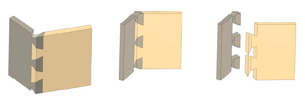
For a long time, I imagined that the tiles could utilize complex printed 3D dovetail features to mechanically join the tiles to each other. I figure with some work it would be feasible to create a process to automatically create these dovetails based on the assembly/pull direction they would need assembled in. That seemed feasible, but it didn’t account for any way to keep them joined together, and even worse, there was no clear path to making that idea something you could easily put on, take off, and latch together.
My good friend AJ at Lucid Drums specializes in repairing traditional african drums. I was looking at the tension lines that were all interwoven and the way it all just felt so taught and springy and durable, it got me thinking seriously about lacing a boot up in a similar fashion. Looking at my angular low poly boot concepts, it seemed feasible to string together the tiles somehow, but this seemed complex as routing the rope between all the tiles might leave some unstrung or create tight bends that would cause too much friction. But just maybe there was something to that idea.
Around the same time I was chewing all that over, I came across a post on facebook with a spiral cut orange peel unwrapping to appear like the familiar “f hole” shape you see in violins and other musical instruments. I went and cut myself and orange that way and had an ahh ha moment. A foot in a ski boot and this orange could both utilize the same spiral unwrapping approach to flatten the 3D surface in a way that a tension line could route through efficiently.
One decision I had been thinking over, is once the ski boot shell geometry is obtained and you have that low poly exterior, you could build each tile off each flat face, OR you could potentially create a more complex “node” tile that further broke down that low poly shape with intermeshing geometries so that the load bearing edges of the mesh were individual tiles and not seams? The idea of the mesh geometry vs the tile prints having an offset element to them was interesting as well; they don’t HAVE to line up with each other.
image of simple tile vs node tile
Through all of this, things started to come together. I thought of a chinese finger trap toy and the mechanism that it uses to tighten; Inter woven biaxial tube braiding. This was essentially the process from my orange peel experiment, but executed in opposing directions to divide the surface further.
image Cut an orange this way
This biaxial weaving is the same process used to make the colorful jackets of paracord rope. So then I thought, if this tube braid could be appropriately deformed and routed around the heel and forefoot, that could be a path to close this boot. Upon thinking about it more, this started to look very intriguing. The boot could potentially be loosely held together like a chainmail and could be simply slipped on to the foot loosely, then tensioned (via some means) so that the tiles were pulled together. I found that this is an emerging field of technology referred to as meta bead structures, and indeed, they can, when correctly designed, create stiffness-tunable structures that can carry extreme loads upon entering a “super-jammed” state. Now that just SOUNDS cool, and there was research to support digging into this path, so I started going forward with it.
I chewed these ideas over for a long time while setting up this site before finally taking the time to sit with my iPad and draw. First, I took a previous ski sock foot sketch I had with a good angle, and had chatgpt kick me out a photorealistic ski sock wearing foot to draw over, because the original sketch wasn’t amazing and I didn’t want to redraw it. I then sketched out construction planes to bend the braid path around the heel and forefoot, and approximated the circumference of the boot at those points. I split those into 8 segments, and connected the vertexes with the next adjacent one on the following layer. This laid out my spiraling cord network. I then saw clearly that with this type of cord path my tiles would be likely based on 4 inputs of the cord paths, not the three sides of the triangle. I assigned the crossover point as the center of each tile, and ended up with an 8 sided tile (avoids sharp corners) that rides on two roughly perpendicular tension cords. Inter spaced with those would exist the secondary TPU/TPE printed liner parts. These offset, flexible parts could act to help seal and or hold the boot tiles together via clever featuring and account for expansion/contraction and frictional wear and noise.
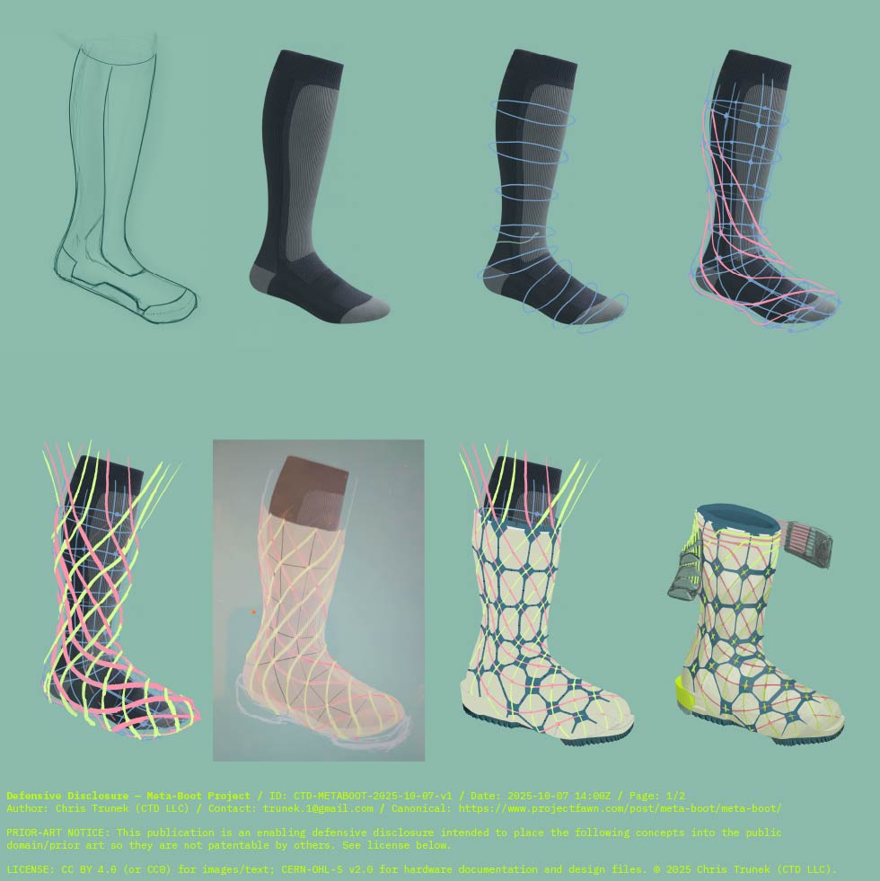
The next element I wanted to at least visualize here was the concept of the break-away heel lug. Since my insight that the binding should not need to be reinvented since it can’t distinguish between normal ski forces and phantom-foot forces, I figured the boot should contain a release modality of its own. For one, the boot is a much more feasible device to detect and distinguish between safe and compromised body positions, but also I don’t want to try to replace all the bindings that are out there; that’s not feasible or ecological. By building the release into the boot, it means any ski that the user decides to ski or demo can be skied confidently knowing the release mechanism has been baked into the boots.
So how would that all work? Well I don’t know yet, but showing something is how we get the idea rolling. My initial thoughts are that these tension paths could be further refined to align more precisely with a user’s anatomy so that when one is leaning back and to the side, certain cord paths could load and unload in such a way that they could “slip” into an over center state that would allow the heel ejection to be able to occur. Only Once that mechanical (or electronic) logic gate was opened, could the heel release be available. It might simply break away or require a spring loaded element like a ski binging uses, but the main point shown is the boot is determining the compromised biomechanical position and only allowing the release to happen in those states. This should prevent this function from limiting skiing performance. Its feasible that this setup might similarly tighten that heel interface under aggressive skiing to ensure that unwanted movement is prevented.
As I was building out the sketch, I could see it was possible to loop opposite strand paths over at the toe so that the effective number of tension cords could be halved. This still left a bunch of literal loose ends to deal with, but I kept sketching the boot anyway. I figured tensioning the whole thing was a different problem to solve.
I explored a few different ideas for closing the boot via tensioning the laces. On the most low end, they could be tied off with knots. this would function for a prototype but not for a product. Maybe a gathered bundle of tension cords making up a neux powerstrap? Maybe they are electronically activated spool tensioners? Sure. Lets roll with that for this concept just ‘cause. We’ll figure it out for real as we go!
At this point I wanted to keep finessing the drawing, but decided it got the points I wanted to convey across. I started feeding the sketch into Chatgpt and Gemini with similarly disappointing results at improving the realism. they kept turning them into hiking boots. What did almost work was a process where I made an image of a skier putting the boot on, and then overlaid it with the sketch and fed it into wan2.5 and Veo3. The Wan 2.5 result was generated on Artlist.io as trial and while the boot still turns into a hiking boot, it does an impressive job of visualizing the lacing changing the boots stiffness for putting it on. The Google result had convincing 3D printed textures but the forms deviated back to more of a traditional pivoting ski boot design. The added voiceover was auto generated and of course the boot breaks down into slop when it is tensioned, but still fun to look at these only partially successful results.
AI images
While the wan2.5 result starts, there is a few seconds of my sketch deforming around in a surprisingly convincingly way. Lets try manually making an oldschool gif out of that. This spun off into a project.
Comments